 |
TimeDomain Corporation has been in research to looking for good sound since its foundation.
One of the basic technological theory is "time domain".
The series of articles were appeared in "Radio Technology" magazine from July to October in 1983.
The concept of "Time domain" is explained very clearly to understand in these articles.
So, please enjoy reading to help your understanding.
Although it had been written more thatn 19 years ago, its theory and technology hold good even today as long as you consider the change of environmental situation.
We will link new material and information from that time down to this day into the main body additionally without changing the original article.(980904)
|
|
- A proposal of New Woofer aiming full-range resistance-control
- by Hiroyuki Yoshii
Force, stronger is better
I studied very hard about low tone domain when I developed sub-woofer called "SL-1".
I actually got two aspects to learn after its release.
First aspect is that Japanese (Oriental) are not so interested in low range. In music listening, they are listening mainly into high range of melodic part ,not listening into low range such as thoroughbass. They can understand well how necessary and wonderful in low range sound if they listen into high quality sound, but it looks like they do not pursue low range quality particularly.
Secondly there are few good low range specified system to utilize sub-woofer. Originally we can expect a wonderful effect when connecting sub-woofer to good low range specified system. However, most people seems to be satisfied with the fact that subsonic sound reproduced.
Now when we consider conventional woofer system from the viewpoint of extra high faithful sound playback, we can not satisfy especially with transient characteristics. Let's think about closed box system known as good transient characteristics. The low range characteristics of the system is determined by Q-factor, however it has been recommended about 0.7 ` 0.9 from the point of frequency r
esponse flatness (Fig. No. 1).
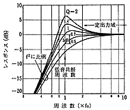 | 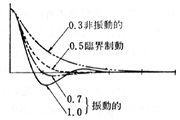 |
| <Fig. No.1> Woofer Q-value and frequency response | <Fig. No.2> Conventional explanation of Q and transient characteristics |
Please see the Fig. No.2 for explanation, Q = 0.5 is the critical control point, and if Q is bigger than that, it will be more vibratile. However from the point of frequency response and vibratile convergence, it has been considered that the ideal value for Q is 0.7 ` 0.9.
It has been explained that if magnetic force is stronger than above value, Q dropped too much and become over-dumped, and as a result the response will be small. Conventional system has been designed based on this theory, however this is a problem.
First of all, my intuition told me it is strange to say that the strong magnetic force is no good.
Also it looks like there is some misunderstanding that the movement of corn-diaphragm is equal to sound pressure (please refer to Fig. No. 10 in June issue). You can get displacement, velocity, and acceleration as shown in Fig. 3, after solving the differential equation of the movement. It looks like 0.7 is suitable for displacement convergence, but not for the acceleration and velocity which is equivalent to sound pressure. The smaller Q seems to have the better transient characteristics.
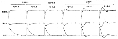 |
| <Fig. No. 3> Proper way of thinking for woofer Q and transient characteristics |
If Q is small, the sound pressure around f0 will become lower. But this can be solved by compensating separately. However it is only true for continuous sound that the bigger Q-system has the higher sound pressure. Probably it will sound smaller for momentary sound since rise-up is not so good.
A proposal of new woofer system
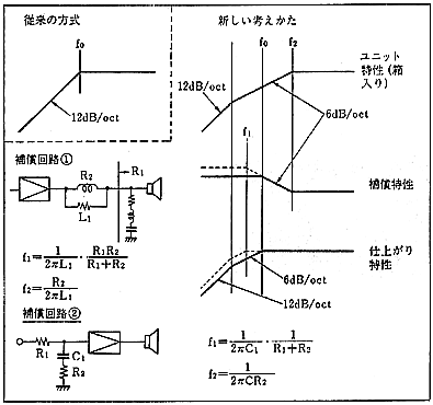 |
| <Fig. No.4> Principles of new way of thinking for woofer. |
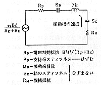 |
| <Fig. No.5> If we make the electromagnetic control resistance R large enough, then distortion will become smaller and transient characteristics will be improved. |
The way of thinking for new system is shown in Fig. No. 4.
If the magnetic force become stronger, not only the transient characteristics will be getting better but also conventional physical distortion will be reduced (Fig. No. 5).
Most distortion will generated from non-linearity of the suspension. If you make the magnetic force stronger, and make the ratio of the suspension impedance in the total impedance lower relatively, then the suspension distortion ratio will also become lower, and the total distortion will be reduced.
In other words, we can say that it is possible to operate according to signals with high magnetic force driving and control force,
even there is a slight prop in damper or edge. We will show some simulation for experimental production in Fig. No. 7 (Fig. No. 6 is a conventional method).
As impedance is pretty big due to electromagnetic control, in case of 10% distortion in supporting part at f0,it will causes only 1% distortion. However it will cause 3% distortion with conventional method as shown in Fig. No. 6.
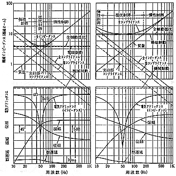 |
| <Fig. No.6> Various woofer characteristics at Q = 0.7 | <Fig. No.7> Various woofer characteristics at Q = 0.3.
Please pay attention to the extent of resistance control domain! |
Also you can understand that with new method, resistance control domain with more than 4 octave range will exist although with conventional direct radiation type , such domain never exist.
So we can expect this system can playback quite different sound to compare with conventional system due to highly improved phase characteristics and group delay characteristics, etc. In experimental system, we modified the system from mass-control to resistance control by installing short horn load, as a result, resistance control range covers all woofer range.
We have listened carefully, low range sound like quite different as we expected.
Every low range instrument sounds real. Each instrument sounds differently, for example, contrabass, cello, bassdrum has different character to compare with the conventional tone which use to sound similarly. It is so differently perceived by every string sound of contrabass. More objectively, it becomes possible to perceive the sound more clearly and separately like "dah!dah!dah!dah!" by the spiccato of contrabass, which used to be perceived like the sound like harmonica. As I mentioned in the previous issue, of course it is true that the sound will be grade up.
We listen into music by paying attention to the delay of low range, and compared with the conventional system according to the sense of hearing (Fig. No. 8). We got the feeling of equal interval each other, however when it comes to our experimental system the story is different. There is no feeling of delay especially. If we get the group delay characteristics from the impulse response , it will be consistent with the sense of hearing perfectly.
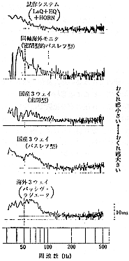 | 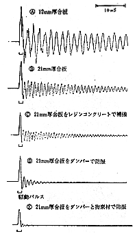 |
| <Fig. No.8> Delay feeling of low range and group delay property. | <Fig. No.9> Effectiveness of panel vibration and preventing vibration effect. |
Reverb Distortion from board vibration
After the adoption of much better unit and method with excellent transient response, the next issue will be the materials for the box and horn.
Vibration will not cause distortion in frequency domain but in time domain, and as a result, it will cause bad influence to playback of music.
We would like to name it as "reverb distortion" since it will linger as shown in Fig. No. 9. It is very hard to detect the reverb distortion with conventional sine-wave measurement method even though it comes out a little bit to frequency response in case of large reverb distortion, however it won't be detected as har monic distortion.
It is very similar to the echo in the room. And we think we can call it echo as same as conventional way since we can clearly tell the difference from reverb distortion according to the following two reasons. One is the big time difference to compare with the original signals, and the other is the reverb generation from different direction with main signals. So, we would like to treat as distortion which is generated in the system and difficult to tell the difference with main signals. Reverb distortion will cause bad influence to the sound of music as same as multipath ghost distortion which is defined in June issue. Bad influence means worsen sound separation, less tone difference, and foul sound with inter-modulation distortion, worsen sound image localization, etc. In the conventional system, it was not a serious problem since reverb distortion was not unpleasant to the ears. On the contrary, it used to be utilized appropriately like poor "Karaoke", which need some reverb.
How to get rid of reverb distortion
(1) Prevent vibration
The biggest distortion will generated in the box. Conventionally, by the reinforcement or adjustment of the materials and shape, they put in shape from the sense of hearing. As a result, generally speaking, the sound from the box was -15dB`25dB to compare with the direct sound from speaker.
The reverb distortion will be 5`20%, but the distortion exists in the part where the signals had disappeared, so it means more bigger sound in point of hearing sense. If you reinforce, when this side is pushed then that side is up, and energy will not be absorbed so it looks like a continuing seesaw game. Even you can adjust the vibration, it is impossible to get rid of reverb distortion.
Fig No. 10 shows an example of changing board thickness. It is possible to adjust by shifting frequency response pattern, but this cannot be a fundamental countermeasure also.
For super high-faithful sound playback, there will be extra requirements regarding reverb distortion.
We have to find out a new method to absorb vibrating energy, nothing to do with conventional method.
See the Fig. No. 9. (A)(B)(C) are conventional conditions and we can say that (C) is the extreme case. Only a super-maniac can do (C) measure. (D) is the case to consider the absorption of vibrating energy and then put together with damping material which has been developed newly. Still, we can not satisfied although both
level and time difference are greatly improved. (E) is the case to add rest ricting material like an iron plate for damping material. This is perfect. We got a hint from the preventing method of vibration for a pole of iron bridge, etc. This is dramatically improved to compare with the conventional data of (A) - (C).
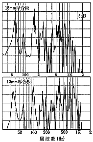 | 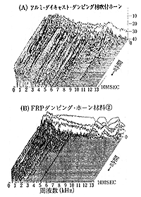 |
| <Fig. No.10> Board vibration of the box. Board thickness will be 1.5 times, also frequency response pattern will deviate 1.5 times toward higher side. | <Fig. No.11> Careful selection of horn material according to accumulated s
pectrum. |
Horn is also prevented from vibration by the same method.
Fig. No. 11 is an example of the improved horn.
We consider it's easy for you to understand that even frequency response(t=0) is the same in total time base, the transient sound will be different. Accumulated spectrum means something arranged in the three dimensional way which remained after cutting each signal's peak in turn. Consequently, frequency response at t=0 means the frequency response at total time base, not momentary frequency response at t=0. Accordingly, the element which did not generated at t=0 will be shown in the curve at t=0. We are likely to misunderstand that the sound was existed at t=0, so please be careful (Fig. No. 12).
 |
| <Fig. No.12> Data results are considerably different according to the difference of time-axis analysis.< |
(2) Absorbing sound in the box
So, we cannot be satisfied with the absorbing sound in a speaker box as it used be.
If you calculate the standing wave mode and frequency, it is well-matched with the measurement value.(Fig No. 13). If you can find out the harmful element and its mode, you can erase it by using absorbing sound material.
Conventionally, we have been attached absorbing sound material to the inside wall of the box, however this is not effective enough for absorbing sound. If we compare the effectiveness for absorbing sound between two cases, one is pasting one piece of absorbing sound mat to wall and the other is locating in the center (Fig. No. 13), the former case is not effective at all, however the latter is very effective to the mode which position will be a node point.
The sound pressure near the wall is strong, but the air doesn't move, so it is for nothing to put absorbing material on the wall.
There is no sound pressure at the position of the node point on sound pressure, however the air is moving strongly, so it works effectively to the absorbing sound material. To put the absorbing sound materials at the most smallest point which is the node point of standing wave is very rational although it is against the common sense. Of course, to make the box filled with absorbing sound ma
terial is the best. Also as an effective method to prevent standing wave, we should adopt one method to make a wall on a slant likewise a listening room.
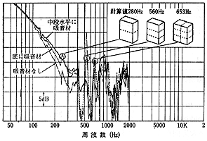 |
| <Fig.No.13> Air vibration mode inside box and absorbing sound effect. |
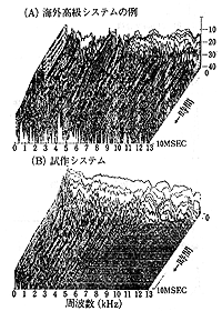 |
| <Fig.No.14> The difference of reverb distortion. |
The results of new system
The Fig. No.14 shows an example of the system which have been considered regarding like this time domain.
If you listen into music through this kind of system, you will deeply realize how the conventional system is lacking in faithfulness. After all hazy distortion like multipath ghost and reverb distortion have disappeared, so far hidden music will come out clearly.
When it comes to sound playback, we always have been considering that speaker system is a neck, but the story will be different from now on.@You can listen to the sound as it is in case you change a cartridge or change an amplifier. You will clearly realize the difference between digital and analog, also compact disk is still far away from we can call it as "ideal" or "dream". Also we will see the defects of source which has been unidentified until now. According to the same reason, we will improve our thought on the limits of aud
io after realizing what an excellent music was recorded in a disk.(To be continued.)
|